How to Prevent Corrosion in Electronics and PCBs
Overview & Key Takeaways
- Moisture and contamination are the primary drivers: Humidity, condensation, salts, ionic residues, and airborne contaminants create conductive pathways and trigger electrochemical reactions on PCB surfaces.
- Corrosion causes multiple failure modes: Including leakage current, short circuits, electrochemical migration, dendrite growth, increased contact resistance, and long-term reliability degradation.
- Corrosion prevention is most effective when designed into the product early in development: Addressing protection strategies during design is typically more reliable and cost-effective than post-failure remediation.
- Conformal coatings are a primary protection strategy: Acrylic, silicone, urethane, epoxy, and Parylene coatings each offer different tradeoffs in barrier performance, thickness, chemical resistance, and reworkability.
- Parylene provides exceptional conformality: Vapor-deposited Parylene creates pinhole-free, ultra-thin films that protect complex geometries and miniaturized assemblies where liquid coatings may not achieve consistent coverage.
- Environmental testing validates reliability performance: Humidity exposure, salt fog, thermal cycling, and HAST help engineers evaluate corrosion resistance before deployment.
Quick Answer
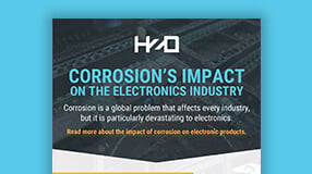
Electronics corrosion occurs when moisture, oxygen, salts, or contaminants react with conductive metals on a PCB or electronic assembly. It can cause leakage current, short circuits, increased contact resistance, intermittent failures, and long-term reliability degradation. Engineers prevent corrosion through environmental sealing, material selection, PCB cleanliness controls, conformal coatings, and reliability testing — ideally designed in from the start rather than addressed after field failures appear.
What Causes Corrosion in Electronics?
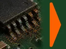
Electronics corrosion occurs when moisture and contaminants create electrochemical reactions on conductive surfaces over time. PCBs, connectors, solder joints, and exposed metals are particularly vulnerable in environments with humidity, ionic contamination, or repeated thermal cycling.
Common corrosion drivers include:
- Humidity and condensation: Moisture forms on PCB surfaces during temperature cycling and creates conductive pathways.
- Salt and chloride exposure: Marine environments, road salt, sweat, and cleaning residues accelerate metal degradation.
- Ionic contamination:Flux residues, handling contamination, and process chemicals — including those left over from PCB manufacturing — increase surface conductivity in the presence of moisture.
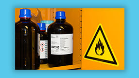
- Industrial pollutants: Sulfur compounds, solvents, acids, and airborne contaminants attack exposed metals and coatings.
- Galvanic interactions Dissimilar metals exposed to an electrolyte corrode at different rates.
- Enclosure ingress: Moisture gradually enters assemblies through seals, vents, connectors, and mechanical interfaces.
How Corrosion Damages PCBs and Electronic Assemblies

Corrosion can produce immediate failures or latent defects that emerge months after deployment. This makes corrosion especially difficult for reliability engineers because failures are often intermittent and difficult to reproduce consistently during analysis.
Leakage Current
Moisture and ionic contamination create unintended conductive paths across PCB surfaces. Leakage current can alter signal behavior, interfere with sensors, drain batteries, and produce unpredictable system operation.
Short Circuits
Conductive corrosion residues can bridge adjacent conductors and create shorts. Fine-pitch assemblies are especially vulnerable because minimal contamination can establish electrical pathways across narrow spacing.
Electrochemical Migration and Dendrite Growth
Electrochemical migration (ECM), also known as dendritic growth, occurs when metal ions move across an insulating surface while under an electrical bias in the presence of moisture. Over time, these conductive metal dendrites, resembling branching tree structures, grow between conductors and eventually create intermittent or permanent short circuits. For dendritic growth to occur, ionic residue, water, and electrical bias all need to be present, and removing any one of these will prevent dendrites.
Increased Contact Resistance
Corrosion on connectors, terminals, and solder joints increases electrical resistance, leading to voltage drops, localized heating, signal integrity problems, and degraded system performance.
Mechanical and Material Degradation
Corrosion also weakens solder joints, connector surfaces, and component leads. Even minor degradation can contribute to failure under vibration, thermal cycling, or mechanical stress.
Moisture + Ionic Contamination + Voltage Bias
Electrochemical Reaction on Conductive Surfaces
Metal Ion Migration and Dendrite Growth
Leakage Current or Short Circuit Formation
Intermittent Failure or Permanent Device Failure
This progression explains why corrosion failures are difficult to diagnose — assemblies may continue functioning for extended periods before intermittent field faults begin appearing.
View our corrosion infographic
Environments That Accelerate Electronics Corrosion
Engineers should evaluate corrosion risk based on actual operating conditions, expected service life, enclosure strategy, and reliability requirements.
| Environment | Corrosion Risk Factors | Common Design Concern |
| Automotive and mobility | Humidity, condensation, road salt, thermal cycling | Long-term PCB reliability across vehicle service life |
| Industrial electronics | Chemicals, airborne contaminants, washdown, humidity | Resistance to corrosive atmospheres and process fluids |
| Medical devices | Biofluids, cleaning agents, and sterilization exposure | Reliability across sterilization cycles |
| IoT and outdoor devices | Rain, condensation, UV exposure, temperature variation | Moisture protection with minimal size/weight impact |
| Aerospace and defense | Humidity, salt fog, altitude, thermal shock | Mission-critical operational reliability |
| Consumer electronics | Sweat, spills, humidity, handling | Warranty reduction and durability improvement |
How Engineers Prevent Corrosion in Electronics
Corrosion prevention is most effective when incorporated early in the design process. Retrofitting protection after failures occur is typically more expensive and less reliable.
Common prevention strategies include:
- Designing for the actual operating environment
- Controlling ionic contamination and PCB cleanliness before coating
- Selecting corrosion-resistant materials and surface finishes
- Reducing enclosure ingress pathways
- Applying conformal coatings appropriate to the application
- Validating performance through environmental testing
Conformal Coatings for Corrosion Protection
Conformal coatings protect electronic assemblies by creating a barrier between conductive surfaces and the surrounding environment. Different coating chemistries offer different tradeoffs in barrier performance, thickness, flexibility, chemical resistance, and reworkability.
| Coating Type | Moisture / Corrosion Protection | Key Strength | Common Tradeoff | Best For |
| Acrylic | Moderate | Easy application and rework | Lower chemical resistance | General-purpose protection |
| Silicone | Good | Flexibility and temperature resistance | Can pool on complex geometries | High-temperature assemblies |
| Urethane | Good | Chemical and abrasion resistance | Difficult to rework | Chemically aggressive environments |
| Epoxy | High | Durability and chemical resistance | Rigid and difficult to remove | High-stress environments |
| Parylene | Excellent | Ultra-thin, pinhole-free conformality | Requires vapor deposition | Miniaturized, high-reliability electronics |
View our corrosion protection webinar
Why Parylene Is Used for Corrosion Prevention
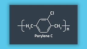
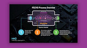
Parylene is a vapor-deposited conformal coating used when engineers require thin, highly uniform protection across complex geometries. Unlike liquid coatings applied by spray, brush, or dip, Parylene forms a continuous polymer film through gas-phase deposition — reaching under components, along leads, and into gaps that liquid coatings may bridge or leave thin.
For corrosion prevention, Parylene offers several advantages:
- Uniform conformality: Consistent thickness across leads, edges, gaps, and under components where liquid coatings may thin or pool.
- Ultra-thin protection: Effective barrier performance with minimal impact on size or weight.
- Pinhole-free coverage: Continuous films reduce localized moisture ingress pathways.
- Strong dielectric insulation: Parylene C dielectric strength typically exceeds 5,000 V/mil, helping reduce leakage current risk in densely packed assemblies.
- Chemical resistance: Resistant to many solvents, acids, and industrial chemicals.
- Biocompatible options: Parylene C and Parylene AF-4 are widely used in medical electronics and implantable devices.
Parylene is often selected when high conformality, thin-film protection, dielectric performance, or coverage consistency is critical for long-term reliability.
When to Consider Parylene Instead of a Traditional Conformal Coating
Parylene is often a strong fit when applications involve:
- Miniaturized or fine-pitch assemblies
- Exposure to humidity, salt fog, condensation, or immersion
- High-reliability requirements with minimal tolerance for failure
- Medical, aerospace, defense, automotive, industrial, or wearable devices
- Weight- or space-constrained electronics
- Complex geometries where liquid coatings may not coat uniformly
View our Parylene Considerations Webinar
Testing Electronics for Corrosion Resistance
Because corrosion is environment-dependent, engineers validate protection strategies through testing that reflects actual exposure conditions.
Common evaluation methods include:
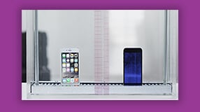
- Humidity exposure testing: Evaluates long-term moisture resistance under controlled temperature and humidity conditions.
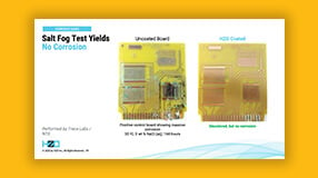
- Salt fog testing: Simulates marine or road salt exposure to accelerate corrosion and identify weak points.
- Thermal cycling: Evaluates coating adhesion and solder joint integrity under repeated expansion/contraction stress.
- HAST (Highly Accelerated Stress Testing): Uses elevated temperature and humidity to accelerate moisture-driven failure mechanisms.
- Condensation testing: Evaluates performance when liquid moisture forms directly on assemblies.
- Chemical resistance testing: Assesses compatibility with chemicals relevant to the target operating environment.
The appropriate test plan depends on product category, operating conditions, regulatory requirements, and expected service life.
Can Corrosion Be Removed from Electronics?
Visible corrosion can sometimes be cleaned from electronic assemblies using appropriate solvents and inspection methods. If you’re dealing with a corroded or water-damaged device, here are the general steps involved:
- Disconnect all power first. Remove batteries, power connectors, and power supplies before any cleaning attempt. This prevents short-circuiting and allows inspection of connectors that may already be corroded.
- Identify affected areas. Look for white or green deposits on battery connectors, charging ports, PCBs, logic boards, SIM card connectors, and other metal contacts.
- Apply a cleaning solution. Isopropyl alcohol at 90% concentration or higher is the most commonly used option. Apply with cotton swabs, gently working the affected area, allowing a brief dwell time before wiping. Note that manual cleaning can often spread rather than remove contaminants, so care should be taken to ensure adequate removal.
- Dry thoroughly. Use a soft cloth or low-heat air. Never apply high heat. The assembly must be completely dry before power is restored.
- Inspect for latent damage. Even after visible corrosion is removed, underlying damage to conductive surfaces, solder joints, and plating may remain and contribute to future failures.

Cleaning is not the same as restoring full reliability. Corrosion can leave latent damage that is difficult to detect visually and may manifest as intermittent failures later. For OEMs and product engineers, prevention is significantly more reliable than post-failure remediation.
Engineering Checklist: Reducing Corrosion Risk
- Define the real-world operating environment and expected service life
- Identify moisture, salt, chemical, and contamination exposure risks
- Review PCB layout and conductor spacing for electrochemical migration risk
- Control ionic contamination before coating application
- Evaluate conformal coating options against environmental requirements
- Consider Parylene for miniaturized or high-reliability assemblies
- Validate protection strategy through environmental testing
- Design corrosion protection into production processes early
Frequently Asked Questions About Electronics Corrosion
What causes corrosion on circuit boards?
PCB corrosion is most commonly caused by moisture, oxygen, ionic contamination, salts, and electrical bias acting on conductive metal surfaces. Flux residues and handling contamination left over from manufacturing can increase surface conductivity and accelerate corrosion when moisture is present — particularly in environments with repeated thermal cycling that causes condensation to form and evaporate over time.
Does humidity damage electronics?
Yes. Humidity can initiate corrosion, leakage current, electrochemical migration, and short circuits — especially in environments with repeated thermal cycling and condensation. The risk compounds over time as ionic contamination accumulates on unprotected surfaces with each condensation cycle.
Can conformal coating prevent corrosion?
Conformal coatings reduce corrosion risk by creating a protective barrier between the assembly and environmental exposure. Protection effectiveness depends on coating chemistry, thickness, coverage uniformity, and application quality. Parylene typically provides the highest barrier performance due to its vapor-deposition process, which achieves uniform, pinhole-free coverage on complex surfaces where liquid coatings may have thin areas with insufficient protection, and/or thick areas where coating pools, which may lead to mechanical damage after undergoing thermal cycling due to mismatched coefficients of thermal expansion (CTEs).
What is the best coating for PCB corrosion protection?
There is no single best coating — the right choice depends on the application. Acrylics offer easy rework for general-purpose use. Silicones withstand wide temperature ranges. Urethanes and epoxies provide strong chemical resistance. Parylene offers the highest conformality and barrier performance, making it well-suited for miniaturized, high-reliability, or medically implanted electronics. See the comparison table above for a side-by-side overview.
Can Parylene protect electronics from corrosion?
Yes. Parylene forms a thin, pinhole-free polymer film across all exposed surfaces — including under components, along leads, and on sharp edges — that acts as a barrier against moisture, ionic contaminants, and corrosive chemicals. Its vapor-deposition process ensures uniform coverage on geometries where liquid coatings cannot achieve consistent thickness.
How long does it take for corrosion to damage electronics?
Corrosion can begin within hours of moisture exposure or remain latent for months before causing failure. The rate depends on humidity, contamination, voltage bias, thermal cycling, and the presence of protective coatings.
Protect Electronics Before Corrosion Becomes a Field Failure
Corrosion prevention is ultimately a design and reliability challenge. Engineers must account for operating environments, contamination risks, coating selection, and validation requirements before products reach the field.
HZO helps companies protect electronics from corrosion, moisture, and harsh environments with thin-film coating solutions including Parylene. If your team is evaluating conformal coating options for a new product or reliability improvement program, request a coating evaluation for your specific application — or explore our protection capabilities to learn more about what Parylene coating can do for your design.
Biocompatible Coatings - Coating Techniques, Applications, More
Dielectric Constant of Insulator Materials: Formula, Table of Values
What is Thermal Conductivity? Explanation, Measurement, Uses


Understand the Capabilities of Thin Film Coatings With Our Resource Page
Understand UL94 Rating - Testing, How to Choose a Material, and More
Learn About HZO Parylene With Our Resource Page

What's the Difference Between Hydrophobic Coatings and Hydrophilic Coatings?
How To Design a Waterproof Product With IP Ratings

NEMA Enclosure Ratings vs IP Standards
Arc Resistance - Concepts And Testing Explained

Dielectric Strength - Formula, Testing, Table of Values

Dielectric Constant of Insulator - Materials, Formula, Table of Values

Military Standards for Safeguarding PCBAs
Tensile Strength at Yield - Testing, Definition, Material Selection
Elongation At Break - Definition, Testing, Material Selection
Elongation Yield Overview - Unit of Measurement, Data, Testing
Young's Modulus of Polymers - Measurement, Calculation, Material Selection
Dissipation Factor - Definition, Measurement, Variables

Volume Resistivity - Definition, Measurement, Implications For Product Design

Biocompatible Coating Material

Transparent Polymers - Applications, Material Selection
WVTR - Coating Standards, Testing, Material Selection

What is the Index of Refraction? Measurement, Definition & More
What is Thermal Conductivity? Explanation, Measurement, Uses

Polymer Glass Transition Temperature – Material Properties, Impact

What is Coefficient of Linear Expansion? Formula, Units & More

Coating Complex Geometries Video
Learn About the Costs of Corrosion
Safeguarding with Nanocoatings Webinar

Understand How to Avoid Premature Product Failure
Learn About Waterproof and Corrosion Resistant Coatings

Prevent Electronic Failure Webinar
Learn About the Thin Film Coating Properties and Processes In Our Webinar

The Difference Between "Hydrophilic and Hydrophobic" Coating Properties
Why You Need HZO Protection For Your Electronics

HZO Coating Demo Video
Learn about Protective Coating Methodologies With Our White Paper